
ISO 286 Shaft & Hole Tolerance Calculator
ISO 286 Shaft & Hole Tolerance Calculator
Calculate ISO 286 tolerance deviations and limit sizes for holes and shafts.
| Parameter | Hole | Shaft |
|---|---|---|
| Nominal Dimension | ||
| Tolerance Class | ||
| Degree | ||
| Lower Limit Deviation | - | - |
| Upper Limit Deviation | - | - |
| Minimum Value | - | - |
| Maximum Value | - | - |
DISCLAIMER
The tolerance calculations provided on this website are for reference purposes only and are based on nominal dimensions and standardized ISO 286 tolerance data. Actual manufacturing results may vary depending on material behaviour, process capability, measurement conditions, temperature, surface treatment, and other production-specific factors.
While every effort has been made to ensure the accuracy of these calculations, Stepstone Dış Tic. Ltd. Şti. makes no warranties or representations regarding their completeness, accuracy, or suitability for a particular application and accepts no liability for any loss or damage resulting from their use. Users are responsible for verifying all dimensions, tolerance classes, applicable standards, and calculated values before making engineering, purchasing, inspection, or manufacturing decisions.
What Does the Tolerance Calculator Calculate?
The calculator uses the entered nominal size and the selected tolerance classes for the hole and shaft, to determine their lower and upper deviations and resulting minimum and maximum permissible sizes.
The results include:
- Lower limit deviation
- Upper limit deviation
- Minimum permitted dimension
- Maximum permitted dimension
- Separate results for the hole and shaft
Comparing the resulting hole and shaft limits can help users review whether a selected tolerance combination is likely to produce a clearance, transition or interference condition.
How to Use the Calculator
- Select the required unit system.
- Enter the nominal dimension.
- Select the fundamental deviation tolerance position and degree.
- Review the calculated deviations and dimensional limits.
Use the same nominal dimension for the mating hole and shaft unless the engineering design specifically requires otherwise
Understanding the Results
Lower limit deviation is the difference between the nominal dimension and the smallest permitted dimension.
Upper limit deviation is the difference between the nominal dimension and the largest permitted dimension.
Minimum value is the smallest acceptable finished dimension.
Maximum value is the largest acceptable finished dimension.
The functional fit depends on the combined limits of both mating components. Manufacturing capability, measuring method, temperature and surface treatment must also be considered before final tolerances are released for production.
Common Applications
This calculator can support preliminary tolerance planning for:
- CNC-turned shafts
- CNC-machined bores
- Bearing housings
- Bushings and pins
- Locating features
- Fabricated and machined assemblies
- Technical quotations and drawing reviews
Important Engineering Notice
The tolerance values provided by this calculator are intended for preliminary engineering reference. They do not replace the applicable edition of ISO 286, an approved technical drawing, project-specific requirements, inspection planning or professional engineering review.
Actual manufacturing results may be affected by process capability, material behaviour, temperature, measuring conditions, surface treatment and other production-specific factors.
Stepstone makes no warranty regarding the suitability of the calculated values for a particular application. Users are responsible for verifying all dimensions and tolerance requirements before making engineering, purchasing or manufacturing decisions.
Frequently Asked Questions
What is ISO 286?
ISO 286 defines a standardized system of limits and fits for linear sizes, including tolerance grades and fundamental deviations for holes and shafts.
Does this calculator replace a technical drawing?
No. The calculated values should be used as a reference and must be transferred to an approved technical drawing together with all relevant manufacturing and inspection requirements.
Does the calculator include coating or temperature effects?
No. Surface treatments such as anodizing or plating and changes in operating temperature may alter the final dimensions of mating components. These effects must be evaluated separately.
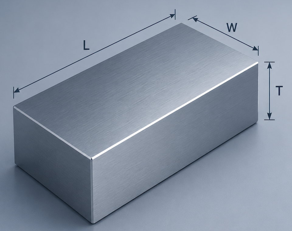
Material Weight Calculations
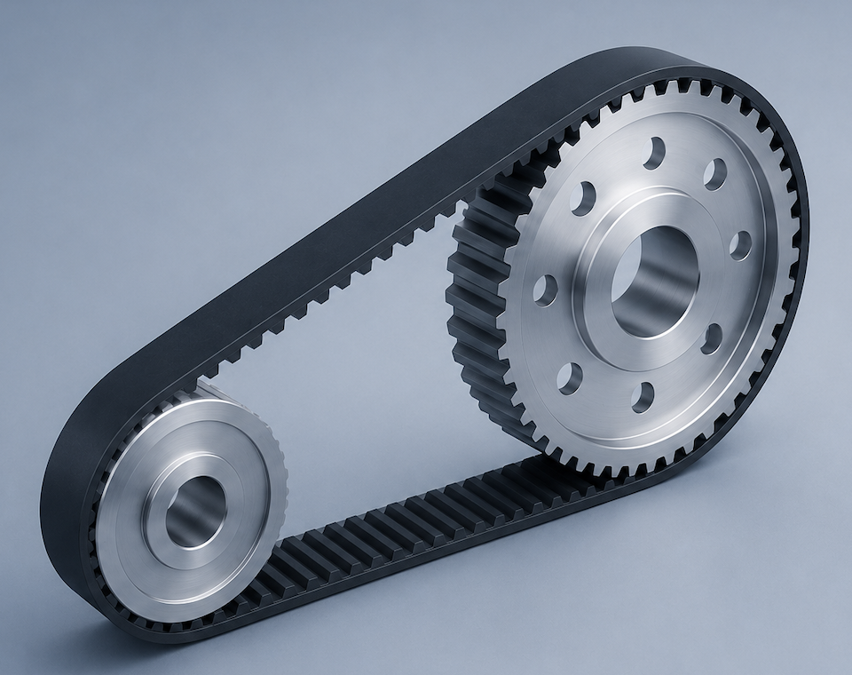
Drive Element Calculations
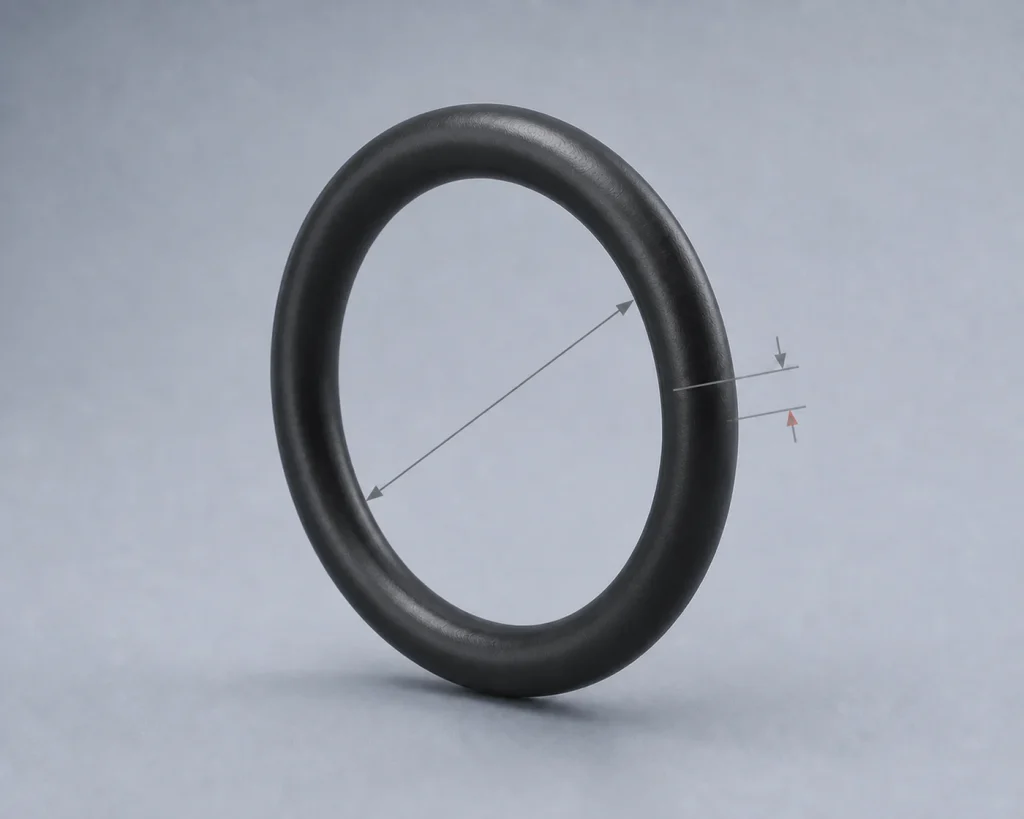
O-Ring Calculator
A Smarter Approach To Manufacturing Projects
Broad Manufacturing Expertise
Through a carefully selected network of manufacturing specialists, we deliver the capabilities needed for complex industrial projects—from individual components to fully integrated production solutions.
One Partner For Every Manufacturing Need
From engineering review and supplier selection to production, quality assurance, and logistics, we manage the entire manufacturing process through a single point of contact.
Built Around Reliability
Every project is managed with a focus on quality, transparency, and delivery performance. From the first inquiry to final shipment, we take responsibility for keeping production under control.